Description
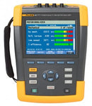
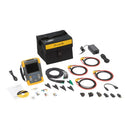
Product overview: Fluke 438-II Power Quality Analyzer & Motor Analyzer
Quickly and easily discover electrical and mechanical performance of electric motors, and evaluate power quality with a single test tool
The Fluke 438-II Power Quality and Motor Analyzer adds key mechanical measurement capabilities for electric motors to the advanced power quality analysis functions of the Fluke 435 Series II Power Quality Analyzers . Quickly and easily measure and analyze key electrical and mechanical performance parameters such as power, harmonics, unbalance, motor speed, torque and mechanical power without the need of mechanical sensors. Fluke 434-II, 435-II and 437-II Power Quality Analyzer users can add motor analysis capabilities to their existing units with the Fluke-438-II/MA Motor Analyzer upgrade kit. The 438-II uses data from the motor rating plate for either NEMA or IEC rated motors to aid the calculation of the mechanical parameters.
Other useful features:
- Calculates mechanical power and efficiency without mechanical sensors. Just connect to the input conductors
- Measures electrical power parameters such as voltage, current, power, apparent power, power factor, harmonic distortion and unbalance to identify characteristics that impact motor efficiency
- Identify power quality issues such as dips, swells, transients, harmonics and unbalance
- Uses PowerWave data capture to capture fast RMS data, and show half-cycle averages and waveforms to characterize electrical system dynamics (generator start-ups, UPS switching etc.)
- Offers waveform capture function to capture 100/120 cycles (50/60 Hz) of each detected event, in all modes, without set-up
- Uses automatic transient mode to capture waveform data at 200 kS/s on all phases simultaneously up to 6 kV
- Automatically calculate motor derating according to NEMA/IEC guidelines
- Fluke Connect® compatible so you can view data locally on the instrument, via Fluke Connect mobile app and PowerLog 430-II desktop software
Key features
The 438-II Power Quality Analyzer & Motor Analyzer helps you effectively evaluate electrical and mechanical performance just by hooking up voltage and measuring current, providing you with an unprecedented level of data.
- Brings key motor analysis parameters like speed, torque and mechanical power and calculates motor efficiency without mechanical sensors
- Includes full power quality and electrical energy analyzer functionality
- Highest safety rating in industry; 1000 V CAT III / 600 V CAT IV
Specifications: Fluke 438-II Power Quality Analyzer & Motor Analyzer
Amps (accuracy excluding clamp accuracy)
| Drive Measurement Details | ||||
|---|---|---|---|---|
| Motor Type | 3 phase asynchronous (induction) | |||
| Power Source | Variable Frequency Drive | |||
| Motor Frequency Range | 40Hz to 70Hz | |||
| Over/Under Voltage from Nominal V/f Curve (%) | -15% to +15% | |||
| Carrier Frequency Range | 2.5kHz–20kHz | |||
| Variable speed drive technology that is covered by the 438-II | ||||
| Inverter Type | VSI only (voltage controlled) * | |||
| Control Method | V/f control, open-loop vector, closed loop vector, drives with encoders. | |||
| Frequency | 40 to 70 Hz | |||
| * VSI drives are the most common drives. The alternative CSI drives are used in higher power applications. | ||||
| Variable speed drive technology NOT covered by the 438-II | ||||
| Inverter Type | CSI (current source inverter) | |||
| Motors type | Synchronous (DC, stepper, permanent magnet etc.) | |||
| Motor Frequency | <40 and >70 Hz | |||
| Mechanical specifications | ||||
| Mechanical measurements can be performed on direct online motors with a 3 wire connection. | ||||
| Motor measurement | ||||
| Range | Resolution | Accuracy | Default limit | |
| Mechanical motor Power |
0.7 kW to 746 kW 1 hp to 1000 hp |
0.1 kW 0.1 hp |
±3% 1 ±3% 1 |
100% = rated power 100% = rated power |
| Torque | 0 Nm to 10 000 Nm 0 lb ft to 10 000 lb ft |
0.1 Nm 0.1 lb ft |
±5% 1 ±5% 1 |
100% = rated torque 100% = rated torque |
| rpm | 0 rpm to 3600 rpm | 1 rpm | ±3% 1 | 100% = rated rpm |
| Efficiency | 0% to 100% | 0.10% | ±3% 1 | NA |
| Unbalance (NEMA) | 0% to 100% | 0.10% | ±0.15% | 5% |
| Harmonics Voltage Factor (NEMA) |
0 to 0.20 | 0.1 | ±1.5% | 0.15 |
| Unbalance Derating Factor |
0.7 to 1.0 | 0.1 | indicative | NA |
| Harmonics Derating Factor |
0.7 to 1.0 | 0.1 | indicative | NA |
| Total NEMA Derating Factor |
0.5 to 1.0 | 0.1 | indicative | NA |
| Notes: | Supports motor design types NEMA A, B, C, D & E and IEC type H and N. Rated torque is calculated from rated power and rated speed. Update rate of Motor Measurements is 1x per second. Default Trend duration is 1 week. |
|||
| 1Add 5% error when selecting Motor design type Other Specification valid for Motor Power > 30% of rated power Specification valid at stable operating temperature. Run the motor for at least 1 hour at full load (2-3 hours if the motor is 50 HP or higher) to obtain stable temperature |
||||
| Product Specifications | ||||
| Volt | Model | Measurement Range | Resolution | Accuracy |
| Vrms (AC + DC) | 1 V to 1000 V phase to neutral | 0.01 V | ±0.1% of nominal voltage 1 | |
| Vpk | 1 Vpk to 1400 Vpk | 1 V | 5% of nominal voltage | |
| Voltage Crest Factor (CF) | 1.0 > 2.8 | 0.01 | ±5% | |
| Vrms½ | 0.1 V | ±0.2% of nominal voltage | ||
| Vfund | 0.1 V | ±0.1% of nominal voltage | ||
| Amps (AC + DC) | i430-Flex 1x | 5 A to 6000 A | 1 A | ±0.5% ±5 counts |
| i430-Flex 10x | 0.5 A to 600 A | 0.1 A | ±0.5% ±5 counts | |
| 1mV/A 1x | 5 A to 2000 A | 1A | ±0.5% ±5 counts | |
| 1mV/A 10x | 0.5 A A to 200 A (AC only) | 0.1 A | ±0.5% ±5 counts | |
| Apk | i430-Flex | 8400 Apk | 1 Arms | ±5% |
| 1mV/A | 5500 Apk | 1 Arms | ±5% | |
| A Crest Factor (CF) | 1 to 10 | 0.01 | ±5% | |
| Amps½ | i430-Flex 1x | 5 A to 6000 A | 1 A | ±1% ±10 counts |
| i430-Flex 10x | 0.5 A to 600 A | 0.1 A | ±1% ±10 counts | |
| 1mV/A 1x | 5 A to 2000 A | 1 A | ±1% ±10 counts | |
| 1mV/A 10x | 0.5 A A to 200 A (AC only) | 0.1 A | ±1% ±10 counts | |
| Afund | i430-Flex 1x | 5 A to 6000 A | 1 A | ±0.5% ±5 counts |
| i430-Flex 10x | 0.5 A to 600 A | 0.1 A | ±0.5% ±5 counts | |
| 1mV/A 1x | 5 A to 2000 A | 1 A | ±0.5% ±5 counts | |
| 1mV/A 10x | 0.5 A A to 200 A (AC only) | 0.1 A | ±0.5% ±5 counts | |
| Hz | ||||
| Fluke 434 @ 50 Hz Nominal | 42.50 Hz to 57.50 Hz | 0.01 Hz | ±0.01 Hz | |
| Fluke 434 @ 60 Hz Nominal | 51.00 Hz to 69.00 Hz | 0.01 Hz | ±0.01 Hz | |
| Power | ||||
| Watts (VA, var) | i430-Flex | max 6000 MW | 0.1 W to 1 MW | ±1% ±10 counts |
| 1 mV/A | max 2000 MW | 0.1 W to 1 MW | ±1% ±10 counts | |
| Power Factor (Cos j/DPF) | 0 to 1 | 0.001 | ±0.1% @ nominal load conditions | |
| Energy | ||||
| kWh (kVAh, kvarh) | i430-Flex 10x | Depends on clamp scaling and V nominal | ±1% ±10 counts | |
| Energy Loss | i430-Flex 10x | Depends on clamp scaling and V nominal | ±1% ±10 counts Excluding line resistance accuracy | |
| Harmonics | ||||
| Harmonic Order (n) | DC, 1 to 50 Grouping: Harmonic groups according to IEC 61000-4-7 | |||
| Inter-Harmonic Order (n) | OFF, 1 to 50 Grouping: Harmonic and Interharmonic subgroups according to IEC 61000-4-7 | |||
| Volts % | f | 0.0% to 100% | 0.1% | ±0.1% ±n x 0.1% |
| r | 0.0% to 100% | 0.1% | ±0.1% ±n x 0.4% | |
| Absolute | 0.0 to 1000 V | 0.1 V | ±5% 1 | |
| THD | 0.0% to 100% | 0.1% | ±2.5% | |
| Amps % | f | 0.0% to 100% | 0.1% | ±0.1% ±n x 0.1% |
| r | 0.0% to 100% | 0.1% | ±0.1% ±n x 0.4% | |
| Absolute | 0.0 to 600 A | 0.1 A | ±5% ±5 counts | |
| THD | 0.0% to 100% | 0.1% | ±2.5% | |
| Watts % | f or r | 0.0% to 100% | 0.1% | ±n x 2% |
| Absolute | Depends on clamp scaling and V nominal | — | ±5% ±n x 2% ±10 counts | |
| THD | 0.0% to 100% | 0.1% | ±5% | |
| Phase Angle | -360° to +0° | 1° | ±n x 1° | |
| Flicker | ||||
| Plt, Pst, Pst (1 min) Pinst | 0.00 to 20.00 | 0.01 | ±5% | |
| Unbalance | ||||
| Volts % | 0.0% to 20.0% | 0.1% | ±0.1% | |
| Amps % | 0.0% to 20.0% | 0.1% | ±1% | |
| Mains Signaling | ||||
| Threshold Levels | Threshold, limits and signaling duration is programable for two signaling frequencies | — | — | |
| Signaling Frequency | 60 Hz to 3000 Hz | 0.1 Hz | ||
| Relative V % | 0% to 100% | 0.10% | ±0.4% | |
| Absolute V3s (3 second avg.) | 0.0 V to 1000 V | 0.1 V | ±5% of nominal voltage | |
| General Specifications | ||||
| Case | Design Rugged, shock proof with integrated protective holster Drip and dust proof IP51 according to IEC60529 when used in tilt stand position Shock and vibration Shock 30 g, vibration: 3 g sinusoid, random 0.03 g 2 /Hz according to MIL-PRF-28800F Class 2 | |||
| Display | Brightness: 200 cd/m 2 typ. using power adapter, 90 cd/m 2 typical using battery power Size: 127 x 88 mm (153 mm/6.0 in diagonal) LCD Resolution: 320 x 240 pixels Contrast and brightness: user-adjustable, temperature compensated | |||
| Memory | 16GB Wi-Fi SD card for standard models or 8GB SD card for /INTL models (SDHC compliant, FAT32 formatted), up to 32GB optionally. Screen save and multiple data memories for storing data including recordings (dependent on memory size). | |||
| Real-Time Clock | Time and date stamp for Trend mode, Transient display, System Monitor and event capture | |||
| Environmental | ||||
| Operating Temperature | 0°C ~ +40°C; +40°C ~ +50°C excl. battery | |||
| Storage Temperature | -20°C ~ +60°C | |||
| Humidity | +10°C ~ +30°C: 95% RH non-condensing +30°C ~ +40°C: 75% RH non-condensing +40°C ~ +50°C: 45% RH non-condensing |
|||
| Maximum Operating Altitude | Up to 2,000 m (6666 ft) for CAT IV 600 V, CAT III 1000 V Up to 3,000 m (10,000 ft) for CAT III 600 V, CAT II 1000 V Maximum storage altitude 12 km (40,000 ft) |
|||
| Electro-Magnetic-Compatibility (EMC) | EN 61326 (2005-12) for emission and immunity | |||
| Interfaces | Mini-USB-B, Isolated USB port for PC connectivity SD card slot accessible behind instrument battery | |||
| Warranty | Three years (parts and labor) on main instrument, one year on accessories | |||
| 1. ±5% if ≥ 1% of nominal voltage ±0.05% of nominal voltage if < 1% of nominal voltage 2. 50Hz/60Hz nominal frequency according to IEC 61000-4-30 3. 400Hz measurements are not supported for Flicker, Mains Signaling and Monitor Mode 4. For nominal voltage 50 V to 500 V |
||||


